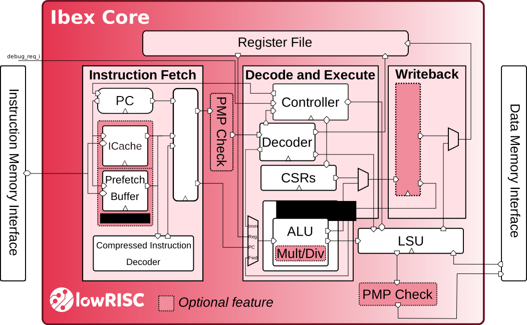
Figure 1 Ibex Pipeline
Pipeline Details
Ibex has a 2-stage pipeline, the 2 stages are:
- Instruction Fetch (IF)
Fetches instructions from memory via a prefetch buffer, capable of fetching 1 instruction per cycle if the instruction side memory system allows. See Instruction Fetch for details.
- Instruction Decode and Execute (ID/EX)
Decodes fetched instruction and immediately executes it, register read and write all occurs in this stage. Multi-cycle instructions will stall this stage until they are complete See Instruction Decode and Execute for details.
All instructions require two cycles minimum to pass down the pipeline. One cycle in the IF stage and one in the ID/EX stage. Not all instructions can complete in the ID/EX stage in one cycle so will stall there until they complete. This means the maximum IPC (Instructions per Cycle) Ibex can achieve is 1 when multi-cycle instructions aren’t used. See Multi- and Single-Cycle Instructions below for the details.
Third Pipeline Stage
Ibex can be configured to have a third pipeline stage (Writeback) which has major effects on performance and instruction behaviour. The details of its impact are not yet documented here. All of the information presented below applies only to the two stage pipeline provided in the default configurations.
Multi- and Single-Cycle Instructions
In the table below when an instruction stalls for X cycles X + 1 cycles pass before a new instruction enters the ID/EX stage. Some instructions stall for a variable time, this is indicated as a range e.g. 1 - N means the instruction stalls a minimum of 1 cycle with an indeterminate maximum cycles. Read the description for more information.
Instruction Type |
Stall Cycles |
Description |
|---|---|---|
Integer Computational |
0 |
Integer Computational Instructions are defined in the RISCV-V RV32I Base Integer Instruction Set. |
CSR Access |
0 |
CSR Access Instruction are defined in ‘Zicsr’ of the
RISC-V specification. Note that most CSR writes flush the
pipeline, so the instruction immediately following a CSR
write incurs an additional fetch-latency. This is mainly to
ensure ePMP updates are taken into account for the next
instruction fetch check. Writes to |
Load/Store |
1 - N |
Both loads and stores stall for at least one cycle to await a response. For loads this response is the load data (which is written directly to the register file the same cycle it is received). For stores this is whether an error was seen or not. The longer the data side memory interface takes to receive a response the longer loads and stores will stall. |
Multiplication |
0/1 (Single-Cycle Multiplier) 2/3 (Fast Multi-Cycle Multiplier) clog2( |
0 for MUL, 1 for MULH. 2 for MUL, 3 for MULH. clog2( |
Division Remainder |
1 or 37 |
1 stall cycle if divide by 0, otherwise full long division. See details in Multiplier/Divider Block (MULT/DIV) |
Jump |
1 - N |
Minimum one cycle stall to flush the prefetch counter and begin fetching from the new Program Counter (PC). The new PC request will appear on the instruction-side memory interface the same cycle the jump instruction enters ID/EX. The longer the instruction-side memory interface takes to receive data the longer the jump will stall. |
Branch (Not-Taken) |
0 |
Any branch where the condition is not met will not stall. |
Branch (Taken) |
2 - N 1 - N (Branch Target ALU enabled) |
Any branch where the condition is met will stall for 2
cycles as in the first cycle the branch is in ID/EX the ALU
is used to calculate the branch condition. The following
cycle the ALU is used again to calculate the branch target
where it proceeds as Jump does above (Flush IF stage and
prefetch buffer, new PC on instruction-side memory
interface the same cycle it is calculated). The longer the
instruction-side memory interface takes to receive data the
longer the branch will stall. With the parameter
|
Instruction Fence |
1 - N |
The FENCE.I instruction as defined in ‘Zifencei’ of the RISC-V specification. Internally it is implemented as a jump (which does the required flushing) so it has the same stall characteristics (see above). |
Zcmp Push/Pop |
2 - N |
The cm.push/pop instructions as defined in ‘Zcmp’ of the RISC-V specification. Internally, they expand to multiple register load/store operations combined with stack pointer adjustments, so their latency corresponds to the total number of instructions issued and the memory latency. |
Zcmp Move |
2 |
The cm.mvsa01 and cm.mva01s instruction as defined in ‘Zcmp’ of the RISC-V specification. Internally, they are implemented as two addi rd, rs1, 0 instructions. |
Note
Zcmp interrupt and exception behaviour
Interrupt masking: Interrupts are suppressed for the duration of a Zcmp pop commit sequence and for the Zcmp move operations. The sequence therefore appears atomic to the interrupt controller. That is, from the stack update to the return jump of the
cm.pop*instructions and the entirecm.mv*instructions.Debug-mode entry: Debug-mode entry is blocked during the entire Zcmp instruction expansion sequence.
minstret counting: An entire Zcmp push/pop sequence (regardless of how many register load/store micro-operations it expands to) is counted as a single retired instruction in
minstret.Exception/interrupt during expansion: If an exception or interrupt is signalled before the commit sequence has started, the Zcmp state machine is flushed and the partial sequence is abandoned. Restarting is safe because the Zcmp spec requires idempotent memory for push/pop, and
spis adjusted last, so partial micro-ops can be replayed without side effects.